Sunday, August 13, 2017

When things go horribly wrong with your 3D printer

I've been printing a lot of parts lately. My printer (an Anet A8 w/ mods) has been quite reliable using my process. My process involves printing on glass, w/ Elmer's glue stick on the surface (more about that later).
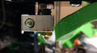
I have IPWebcam running on an old cell phone so I can monitor the printer from upstairs or outside of the house. I had started a print with a fairly full build platform and checked it before going to bed. I saw one corner didn't look quite right, but I was tired and thought I'd sort that out in the morning. Big mistake! Here's what I woke up to:
Oh, and this was on the floor:
OK, I'm sure this is fixable. Well, not the glass, but I got that for free, so I'm sure I can get more. I need to clean off that hot end though! Chipping it off isn't an option.. way too difficult. I raised the Z and moved the X over the center of the build platform to give me some space to work. I turned up the extruder temp to 200 degrees C. As it reached that temp, I could wiggle that mass. I was able to get it tilted off the hot end and then carefully pulled the heating element out by grabbing the cooler part of the wire further away from the element. Now, I had to shut off the heat because when it's not in the block, you get thermal runaway as the thermistor can't tell it's already hot enough.
While things were still hot, I grabbed a heavy shop paper towel and folded it over a couple of times. I could drag that across the heat block and extruder tip. It picked up all of the melted PLA after several tries. Be careful to not wipe the hot end with your fingers behind the paper towel. Hold a longer piece between your 2 hands and rub it over the PLA on the hot end so it drags the plastic off.
I cleaned the heating element and as much of the thermistor in much the same way. I was able to heat it up again and re-insert it to re-heat the hot end when I wanted to get more PLA off. I was also able to get the paper towel in above the heat block and clean off the threaded tube.
I found the block was loose and so, I used some pliers to carefully twist it tight again. That threaded tube is not super strong, so don't torque it too much! I cleaned out the hole where the heating element went and reinserted the element. In the past, I had a single layer of aluminum foil wrapped on the element so it was pretty snug in the heat block. I did that again and got it all back together. It's looking pretty good now!
The root cause of all of this: One corner of the part had lifted up where I didn't have good glue coverage. It hardened and caused the hot end to crash into it. Not sure where the PLA started globing up, but I assume at some point, part of the part that lifted became stuck to the hot end and started picking up new plastic that was being extruded. It all got very bad from there. It knocked into the binder clips holding the glass, the glass moved (part of a layer was printed at an angle at some point). The glass eventually ended up on the floor, broken. Lesson here, keep an eye on things! Most stuff goes wrong in the first layer. The chance of things going south vastly decreases as the layer count goes up (assuming you have good adhesion and don't run out of filament!).


Monday, May 22, 2017

Shapeoko 3 Work Holding System

What I'm going to describe is so useful, I'm not sure why Carbide3D doesn't offer it out of the box! Our FIRST robotics team decided to purchase a Shapeoko 3 XL to allow us to machine larger parts, but also fit it through doorways in our school. Our team has limited space and needs to pull everything out of a store-room to start working on any project. This version of the Shapeoko has a pretty hefty 3/4" MDF bed that bolts to the steel frame. It came pre-drilled for the M5 socket-head bolts. We saw videos from Winston Moy and others about the finer points of Shapeoko 3 ownership and were especially impressed by the hold-down system he showed for his Shapeoko 2. It involved threaded inserts and slotted wood pieces that were used to hold down material being machined with the help of bolts into the threaded inserts arrayed around the MDF bed. I've linked to the video to help illustrate.

We decided to tackle this and were able to get the insert part # by pausing the video and ordered this from McMaster-Carr. Further reading about these inserts indicated that they would be strongest if we inserted them from the bottom of the MDF. The flange provides additional strength that way so the inserts won't pull out. We wanted to be sure many students on our team would be able to use this machine for years to come, without damaging it.

We had to decide how many inserts to install and how to arrange them on the board. We use SolidWorks for all of our CAD and decided to use the LinearPattern tool to lay out holes in the MDF board. It was a huge help since the starting offset and spacing could be tweaked very easily. We ended up centering the pattern left-to-right (along the machine's X axis) and because of how the Z axis hangs off the front of the X axis gantry, we aren't able to reach the far back of the MDF, so we left a row blank on the back edge. It was easy to generate a dimensioned drawing from SolidWorks which helped when machining the holes.


Next was the hole profile. We had a little trouble generating g-code using the tools Winston used (probably due to lack of experience), so ended up designing the hole profile in SolidWorks and using HSM Xpress to define the tool paths. We chose to use 1/2" inserts in the 3/4" MDF, so there would be some room to level the bed by machining it with a fly cutter.


Since the Shapeoko cannot reach the extents of the bed due to mechanical limitations (except the front edge), we knew we'd need to position the MDF a few different ways to allow the hole pattern to be machined in. We also knew if we were going to machine all the way through, we'd need a waste board underneath to prevent us machining into the steel frame. We also got some 2" M5 bolts to reach from the top of the MDF (which is upside down) through that and the waste board and into the threads in the frame. After securing the MDF by shifting it to overlap the middle set of holes with the existing holes in one end of the MDF, we were ready to start.

Using a ruler, we measured the offset of the 1st hole. This would be the anchor point for the entire grid of holes, so measure carefully! We used an 1/8" flat end-mill to machine our holes. Using Carbide Motion, it's pretty simple to position the bit over the hole. Bring it pretty low over the MDF, adjust X and Y to line up with the marks. We use the paper trick to adjust the Z axis. Drop the Z by small increments while moving paper underneath the bit. Once the paper sticks, raise the Z 1 step, remove the paper and drop the Z back down 1 step. Now, set zero for all axis and you're ready to start!

After running the code for the hole, the bit ends up off-center, so before moving to the next hole, it's a good idea to use reset X-Y (through Carbide Motion). Then, you can jog the machine in either X or Y direction 3 inches to start the next hole. Once the X-Y are set, repeat the Z setting procedure with the paper and reset zero for all axis. Rinse and repeat till you need to reposition the board to reach more holes. Eventually, you'll end up with a board that looks like this.


Pretty slick! Now, you can install that on the machine and use your hold-downs!


Sunday, August 3, 2014

How to replace Audi A5 2.0T air filters

My car is coming up on 75K miles and I decided to tackle some of the service items myself. I ordered replacement air filters for the engine and cabin of Amazon.com. One was the OEM Mann filter, the other made by TYC. I'll talk about the engine air filter first. As you can see in the pictures, the airbox has some Torx screws (6 in all), a connector and a hose. The air hose is pretty simple to remove with a large flat blade screwdriver. The thoughtful folks at Audi molded a little tab into the hose so that when you loosen and tighten the hose clamp, it doesn't try to spin away from the screwdriver! The MAF connector is pretty trivial to remove as well. Removing this connector is optional I think, but I liked being able to fully remove the top of the air box.


The Torx screws are captive and so once they are loose, don't try removing them. After they are all loose, you can simply lift off the cover. Below, you'll see how the filter fits. The bottom was a lot dirtier! The new filter fits the same way. Be sure that the rubber edge of the filter fits within the lip of the airbox before reassembly. As they say, it's the reverse of disassembly.


Next, I wanted to tackle the cabin air filter. On a previous car, it was accessed via the air plenum. I removed the cover on mine by removing the two fasteners shown with the arrows in the 2 pictures below. They just screw off and can be set aside.


The cover lifts off starting at the front edge and pulls forward. Once I got mine off, I found the air intake. Hmm, no filter!? I noticed something else, leaves! I would never have found those without looking under the plenum cover. I recommend everyone that lives where leaves fall from the trees (isn't that most places?) should clean out the air plenum yearly! The leaves will rot and also trap moisture which is a bad thing for the painted metal!


After vacuuming that out and replacing the cover, I decided the cabin air filter must be inside the car. The filter I bought came with instructions on how to replace it, so that helped! The filter is accessed by removing a foam panel behind the glovebox. You'll need to get down into the passenger footwell to get at this. Notice the 3 screws that can be easily removed with your fingers. Once those are off, carefully pry the front edge of the foam panel down. You might be able to push the whole panel back a little to clear the plastic on the front edge. Try not to rip it since I think that could happen pretty easily.


With that panel off, you can see where the filter is held. The plastic retainer is removed by pushing the little handle to the right an inch or less. Then, it can be pulled off and out of the way. The old filter has to be pulled down and out. I had to bend my filter a little to clear the carpet.


Here is my new filter above the old one. Definitely a lot cleaner! Also, see the little tab on the new filter (shown by the arrow). This isn't a big deal and probably helps pull it out later, but it gets in the way of the retainer, so I folded it flat against the filter first.


I hope this helps! The other major item on my 75K service is spark plugs and I won't write that up since I found a very good how-to already posted.

Friday, May 16, 2014

How to replace an Audi A5 backup light

I had a warning pop up on my A5 and thought I could fix it myself. I've replaced bulbs on all of my other cars. When I looked for information in the owner's manual, I was annoyed to see "take it to the dealer". That'll never do! I tried looking on-line, but nothing very helpful was available. I decided to dive in and here are the details. First, I bought the replacement lamp spec'ed in the book at the local Walmart. It called for a 921 bulb. Then, I went home and had a look around the trunk. I wasn't sure if the light was in the trunk lid, but soon found flaps on either side of the lid behind the lights. Here are what my lights look like (it's a Premium Plus w/ LED lights)
Under the trunk lid, open the flap. Carefully pull till the 2 retaining clips pop free. Once open, you'll notice 2 long nuts that are part of 2 retaining clips. Use a wrench or large flat-blade screw driver to loosen the nuts and remove the clips.

Once the clips are removed, unplug the electrical connector and you'll be able to lift out the light assembly.
The reverse light is located in the corner, turn it slightly counter-clockwise.
Now, you can replace the bulb.
As they say, reassemble in reverse order!

Any questions, please ask!

Wednesday, April 9, 2014

Lights In a Jar

I've liked blue lights since I was a kid. I noticed the blue lights when we drove past the airport. I like blue glass also. It's a pleasing color. I was drinking some wine recently and was struck by the blue bottle.


I thought it might look nice if illuminated from inside. Being a little creative, I thought about fun ways to light the bottle from the inside. My first thought was using white LEDs. I though, why not put some strings of LEDs inside at different angles. The next day, I remembered I had an Adafruit Trinket laying around and wondered if it would fit in the mouth of the bottle. It does, with room to spare! How many PWM outputs? 3? nice! Each can drive 20mA, so hmm, ok, with a transistor, could drive some more LEDs off each output. I settled on 3 strings of 4 LEDs hung at different heights in the bottle. I thought I could drive them to fade out at regular intervals to add some interest and make it a little more dynamic.

I wrote some code and soon found that the 3rd PWM output wasn't enabled by default using the Arduino IDE. There is a workaround on the Adafruit forums. Their whole site was down for maintenance when I was working on the code, so I didn't get that fix in until later that evening. I made a video of the problem prior to that, so you can see the earlier code in action. I've posted the code on github.

Let me take a little time to talk about the code for those not so familiar with software design (since that is my profession). If you follow the github link and look at LightsInAJar.ino, you'll find the normal setup and loop functions, but also more. The PWM4_init and analogWrite4 functions come from that forum post and handle the pint 4 PWM problem I mentioned. Setup is pretty straight forward in that it sets the 3 output pin modes, then configures the troublesome PWM output. After that, we get into some logic for a state machine. For those unfamiliar, state machines have been around for a long time. They are sometimes helpful in software since they consist of discrete states and transitions between states. In this case, I've defined 4 states for each of the outputs;
// states for 3 led strands
// 0 = off
// 1 = turning on
// 2 = on
// 3 = turning off

The code in the update function handles what to do in each state. If you check the main loop, it calls update for each LED, then delays 20 milliseconds and repeats, forever. So, for each LED, update is called every 20 milliseconds. Each state increments a counter since I want the LED to remain in each state for a period of time. It also checks a limit to see when it is time to move to the next state. For states 0 and 2, it simply waits and moves to the next state. For states 1 and 3, the PWM value for that pin is also changed. In those states, we are either turning the LED on or off, so we pass the counter value to analogWrite4 when turning the light on, and we pass 128-counter when turning the light off (instead of decrementing the counter. All of the state machine logic is the same for each LED. I set up the state variables differently for each LED to make each output start at a different state, and counter value. I also used "pass by reference" to allow me to pass variable into the update function and use those external variable directly within the function.

Enough about the code! I have single LEDs turning on and off, but I still needed to design the transistor driver circuit and since I'm a little rusty on that, I looked for an on-line circuit simulator. I found CircuitLab which worked pretty well, but for serious use, they need a paid acct. If anybody can give me a pointer to some decent open source visual circuit simulation, I'd be very happy!
I set up a simple driver circuit, designed to handle 4 LEDs at 20mA each. Here's a picture I took of the simulation.

I wired this up and it worked very nicely! I will point out that I am using blue LEDs for breadboarding. I ordered some compact white LEDs from eBay and hope to get those within a week. They were $2.30 for 100, which is way more than I need, but 1/10th the price of RadioShack (which is where I picked up the transistors and resistors).


To power this, I plan on using an old wall adapter for a bluetooth headset. Those put out 300mA and will be enough for this since 12 LEDs at 20mA each + 12mA for the trinket adds up to 252mA. I plan on including a proper power switch as well since I want to power the whole thing off. Otherwise, I may have simply connected a pushbutton to the trinket and made a software switch. I'll follow up with the rest of the project soon!

Tuesday, February 4, 2014

Eclipse Clock - making the case

I've had the circuit running on the breadboard and the software is in a workable state, so what's next? Well, I could work on the circuit board or the case. I chose the case. My idea was to use MDF (medium density fiberboard) for the back since it is very easy to work with and stable. I also knew I needed a way to cut perfect circles. I have a Bosch Colt hand router that came with a fence bracket. I was able to use part of that along with a 1/2" nylon bushing, screw and wing-nut to make a circle cutting jig. Pictures of that later. First, I had ideas about how the case would look and how it should be put together. As I got to the point of actually making the case, I jotted down a cross-section diagram with dimensions in my notebook.


The dimensions in there are pretty accurate. Let's call the parts "back", "spacer" and "front". The back and spacer are made from 1/2" MDF and the front was made from some curly maple that I got at a local specialty wood store. I chose curly maple since it was interesting to look at and quite hard. I bought a 7" x 15/16" board that I cut into 2 16" sections and jointed and glued together to form a 14"x"16" piece. I made the one dimension 16" so that it was easier to feed through a drum sander. I ran the glued board through the sander until each side was perfectly flat and no glue seam remained.


Now, I had all of my materials and I needed to start cutting circles! I got a 1/4" straight bit for the router and made some test pieces for the back. The problem was that the Adafruit 1M LED strip needed to form a perfect circle with the ends meeting perfectly so the LED spacing would be consistent, even at the joint. 1M circumference results in a 12.53" diameter circle. I adjusted my circle cutting jig to 6.25" (radius). It turns out I needed to try a couple of times. The first back piece was too small (the ends of the LED strip overlapped by about 1/2 LED length.). The second one was too large (too much gap in the ends of the strip). The third one.. the third one was just right! I had very minimal overlap and didn't feel like I needed a 4th!

\

This picture shows the MDF after I've made about 3 passes. You really shouldn't take more than 1/8 of material at a time. The bit would overheat. You can clearly see the jig I made in this picture. The hard part was measuring between the bit and the center of the nylon spacer. I had to use a screw driver to tighten the screw and double check the measurement each time. Notice the 1/2" guide hole in the MDF. That's what guides the entire cutting operation.

I should point out what might be obvious, but not to somebody who is new to this type of thing. You must make the larger diameter cuts first. Cut the outer diameter groove, then I actually went further out and cut all the way through to make the disk. This was how I left that little shelf for the LED strip to rest on. Once the outer diameter is cut, move in and cut the inner radius. Once you cut the inner radius, you can't go back and do the outer radius because that guide hole is no longer part of the piece!

The next thing I made was the spacer. It was a circle of MDF about 3/4" wide. After that, I could start on the maple case front. I chose one side that would be visible on the outside based on the grain pattern I liked. I then cut the opposite side. I drilled a guide hole and started routing the groove on the outer diameter. This maple is definitely harder than MDF! Go slow and make small depth adjustments as you go. It will take a while!


Once the circle is cut out, I had to start on the recessed area. This is visible in the cross section and will be where the electronics live. I made 2 grooves that formed the boundary for the recess. These were 3/8" deep.


Next, I had to remove the rest of the material between those grooves. Doing this with that 1/4" bit would have been time consuming. Luckily, I had a 1/2" bit from another project so I was able to use that to clear the material in 3 passes (many more if you consider advancing the depth bit-by-bit).

Finally, I was done clearing out the recess. I should mention that I had to run the shop vac between each pass due to the amount of sawdust created. Here's proof!


Final step is to remove the center disk and complete the front case shape. I worked on making the groove deeper and deeper, then a final check of my spacer to be sure it fit. This would be the last chance to get in there and adjust the recess area!


Once that was done, some light sanding and checking how it all fit together. I decided to mount the LED strip next to get a better idea of how it all worked when put together. I used about 7 dabs of hot-melt glue to attach the strip. Prior to doing this, I created some space behind the joint in strip. I needed room to attach wires and route them to the interior of the case.


I also used a saber saw to cut a flat on the spacer ring. I figured this would leave plenty of room for the electronics and was part of my original plan when calculating dimensions.


See? Plenty of room for the Arduino Micro and my own small board (which I still need to build!) With everything held together, here's how it looks. I have some rough sanding to do on the outer and inner radius of the front part of the case. I also used a chamfer bit to ease the front edge of the case. I think it looks pretty slick.


Next time, I'll show more about the electronics and the finished look of the case.

Saturday, January 18, 2014

Eclipse Clock

I was initially impressed by a clock I saw called the "Equinox Clock" posted here. The author went into some detail on the construction, but it wasn't a full how-to. I thought about doing my own, but all of the work he did with the separate driver chips and LEDs kept me from getting started. Mostly because of the time investment required. When I saw that Adafruit Industries started selling 1M strips of their "NeoPixels", I thought that would be a great alternative and most of the work spent on the clock would go into other things besides custom circuit boards and interconnects.

I plan on posting all of my plans and code on-line with instructions to help you build your own. I'm calling it "Eclipse Clock" because I think it looks more like a solar eclipse (and I didn't want to steal the name). Here's the part list I'm using;

  • 1M Neo-Pixel strip
  • Arduino Micro
  • DS1307 RTC chip
  • 32.786 KHz crystal
  • CR2032 lithium battery (and holder)
  • push-button switch (N.O.)
  • small Cds cell
  • 4 10K Ohm resistors
  • 1 1000 uF capacitor
  • 5v power supply (4 amps ideally, more on that later)

The clock will consist of an strip of LEDs shining sideways out of a round case. They radiate outwards and end up reflecting off the wall. There is a single pushbutton for setting the clock and changing color scheme between some presets. A real-time clock chip keeps accurate time. Hours are represented by 3 lit pixels, minutes by 1 lit pixel and seconds by another lit pixel. Themes can change color values of these as well as use a separate background color (which could let you have a fully lit ring with dark values for hours/minutes/seconds).

Source code will be on github.

More in a future post, but that's where I'm starting!